

Laser-driven fusion has been firing large-aperture, high-fluence laser systems into targets for decades at facilities such as the National Ignition Facility (NIF) at the Lawrence Livermore Laboratory, Laser Mégajoule, Orion and the various CEA and LOA beamlines. As the science has developed and so refined the approach, inertial confinement fusion (ICF) has moved from a single-shot physics programme to a commercial proposition: inertial fusion energy (IFE). Venture capital and public-private partnerships are increasing in number and ambition, now specifying and buying hardware rather than simply publishing results.
This development brings new challenges and not ones that fusion scientists are necessarily aware of. Components themselves haven’t fundamentally changed. Optics such as large-aperture laser-line mirrors, a high-LIDT windows or Fpolarisers for ICF drivers are, by and large, the same products that high-energy laser laboratories have been purchasing for decades. The change in duty cycle in IFE systems however, fundamentally changes how an optic should be specified, tested and warranted.
Key Highlights
- Repetition rate, not aperture, is the real specification challenge for IFE optics. Systems targeting 1-100Hz compress decades of cumulative ICF shot exposure (e.g., OMEGA’s 50,000 shots over 30 years) into hours or minutes, and existing datasheets don’t capture this.
- Single-pulse LIDT is not a reliable predictor of survival at high repetition rate. What’s actually needed is S-on-1 fatigue data at the intended pulse duration and rep rate, per ISO 21254, and for most proposed regimes this data simply doesn’t exist yet.
- Above ~10Hz, thermal effects (lensing, coating stress, mount distortion) become as important as peak fluence, and a room-temperature acceptance test won’t reveal them.
- Contamination, not the substrate or coating itself, is frequently the actual driver of damage onset at high repetition rate, which means laboratory LIDT data transfers even less cleanly to an operational system than the fluence numbers alone would suggest.
Laser-driven fusion has been firing large-aperture, high-fluence laser systems into targets for decades at facilities such as the National Ignition Facility (NIF) at the Lawrence Livermore Laboratory, Laser Mégajoule, Orion and the various CEA and LOA beamlines. As the science has developed and so refined the approach, inertial confinement fusion (ICF) has moved from a single-shot physics programme to a commercial proposition: inertial fusion energy (IFE). Venture capital and public-private partnerships are increasing in number and ambition, now specifying and buying hardware rather than simply publishing results.
This development brings new challenges and not ones that fusion scientists are necessarily aware of. Components themselves haven’t fundamentally changed. Optics such as large-aperture laser-line mirrors, a high-LIDT windows or Fpolarisers for ICF drivers are, by and large, the same products that high-energy laser laboratories have been purchasing for decades. The change in duty cycle in IFE systems however, fundamentally changes how an optic should be specified, tested and warranted.
The real variable is repetition rate, not aperture
A traditional ICF facility might fire only a handful of times a day, accumulating its lifetime shot count gradually over years or decades. Next-generation IFE systems are targeting a very different regime: repetition rates of 1-10Hz today, with 100Hz cited as a longer-term goal for plant-scale systems. At those rates, a given optic could accumulate tens of thousands of shots not over decades, but within a dramatically compressed operational timeframe, the same cumulative exposure, delivered far faster.
To put that gap in concrete terms: the OMEGA Laser Facility at the University of Rochester’s Laboratory for Laser Energetics, for example, operates at roughly one shot per hour, and its OMEGA Extended Performance (EP) system at 7-8 shots per day, on the order of 10⁻⁴Hz¹. IFE-relevant systems targeting 1-10Hz represent a jump of four to five orders of magnitude in firing frequency, not an incremental improvement.
The drive for a 100Hz rep rate isn’t a purely theoretical target. Diode-pumped solid-state architectures have already demonstrated this combination in practice: hundred-joule-class pulses delivered at a 10Hz repetition rate, 146J, the current record at the time of writing², and, at the higher end of the rate spectrum, pulses in the 10J range sustained at 100Hz for extended operation³.
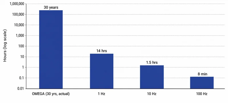
It’s important to highlight the arithmetic behind this development. The Omega Laser Facility reached its 50,000th target shot on 28 October 2025, a milestone accumulated over 30 years of operation across its OMEGA and OMEGA EP systems, at a current operating capacity of around 2,000 shots a year⁴. The same 50,000-shot total would be reached in under 14 hours at 1Hz, in under an hour and a half at 10Hz, and in around eight minutes at 100Hz. An optic qualified against three decades of accumulated shot history at a national research facility is, at IFE-relevant repetition rates, being asked to survive the same cumulative exposure before researchers take a mid-morning coffee break.
Fatigue behaviour, not single-shot threshold, is what matters
A single-pulse laser-induced damage threshold (LIDT) measurement, of the kind widely quoted on datasheets, is unfortunately not an accurate predictor of survival over 10⁶ or more shots. What is actually needed is fatigue data that characterises how the damage threshold evolves with accumulated shot count at the intended pulse duration and repetition rate, following the ISO 21254 test methodology⁵, which formally distinguishes between “1-on-1” testing (a single pulse per test site) and “S-on-1” testing (a defined number of pulses, S, delivered to the same site to establish a fatigue curve).
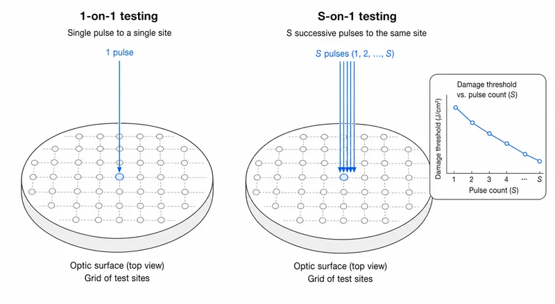
This data is at best, slow to generate and expensive and, for most repetition-rate regimes now being proposed, simply does not yet exist. This is the crux of the challenge for both laser physicists and optical component manufacturers.
Average power drives thermal effects that peak fluence does not
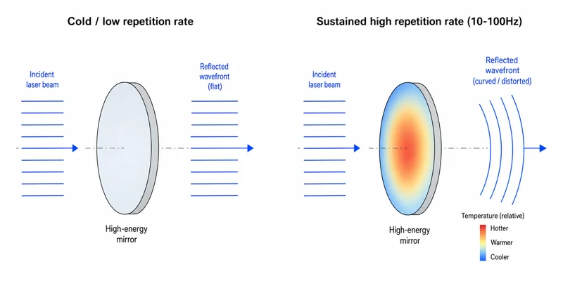
Whilst at low repetition rates, an optic is effectively a static component between shots, between 10 and 100Hz, absorbed energy accumulates faster than it can dissipate, and thermal lensing, coating stress and mount-induced distortion become significant. A mirror that is flat to a fraction of a wavelength cold for example, may not be flat under sustained thermal load. This is rarely captured by a room-temperature acceptance test.
Contamination becomes a repetition-rate problem in its own right
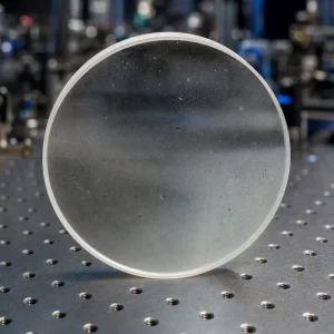
In the environment of a target-chamber, debris and hydrocarbon deposition accumulate with shot count. The onset of damage on optics operating at high repetition rates is frequently caused by surface contamination therefore, rather than being intrinsic to the substrate or coating. This is a further reason why single-pulse laboratory LIDT data does not transfer easily to an operational IFE system.
The honest position, and one that any credible supplier should be willing to state, is that nobody can yet warrant a large optic against 10-100Hz operation for a defined period from first principles, because the underlying fatigue and thermal data simply has not been collected at this scale.
That gap in the data doesn’t remove the need to write a specification today, though. It just means the specification has to be written with the gap acknowledged, rather than papered over with numbers borrowed from a system that never ran at this duty cycle. That’s where the trouble usually starts in practice: not in the physics, which is at least honestly uncertain, but in drawings copied from ICF facilities without being reconsidered for what’s actually being asked of them. That’s the subject of Part Two.
Wrap Up
None of this is an argument against pursuing high repetition rates, it’s simply a case for being clear-eyed about what qualification at those rates actually requires. An optic’s single-pulse LIDT figure tells you almost nothing about how it will behave at shot 40,000 of a 10Hz run. Until S-on-1 fatigue data at the relevant pulse duration and rep rate exists for a given design, any lifetime claim beyond that point is an extrapolation, and should be treated as one. If you’re specifying a system at 1Hz or above, the conversation with your optics supplier should start with duty cycle, not aperture.
If you want to find out more about how we can support your IFE research, please get in touch.
Footnotes
- OMEGA repetition rate: Laboratory for Laser Energetics, “Timeline – 1995,” University of Rochester, https://www.lle.rochester.edu/timeline/1995/, confirms performance verification tests “at a repetition rate of one shot per hour,” April 19, 1995. OMEGA EP repetition rate: “Laboratory for Laser Energetics: OMEGA EP,” LaserNetUS, https://lasernetus.org/facilities/omega-ep, confirms “a full-system shot cycle of approximately 1.5 hours is typical with 7 to 8 shots per day.”
- Divoký, M., Pilař, J., Hanuš, M., Navrátil, P., Denk, O., Severová, P., Mason, P., Butcher, T., Banerjee, S., De Vido, M., Edwards, C., Collier, J., Smrž, M., & Mocek, T. “150 J DPSSL operating at 1.5 kW level.” Optics Letters 46(22), 5771–5773 (2021). https://opg.optica.org/ol/abstract.cfm?uri=ol-46-22-5771
- De Vido, M., Quinn, G., Clarke, D., McHugh, L., Mason, P., Spear, J., Smith, J. M., Divoky, M., Pilar, J., Denk, O., Butcher, T. J., Edwards, C., Mocek, T., & Collier, J. L. “Demonstration of stable, long-term operation of a nanosecond pulsed DPSSL at 10 J, 100 Hz.” https://pubmed.ncbi.nlm.nih.gov/38571028/. See also the related conference report: “Demonstration of a Nanosecond Diode Pumped Solid State Laser Operating at 10 J, 100Hz and Future Applications,” CLEO Europe 2025, https://opg.optica.org/abstract.cfm?uri=CLEO_Europe-2025-ca_8_1
- “A Milestone Achievement: Omega Laser Facility’s 50,000th Shot,” University of Rochester Laboratory for Laser Energetics, 28 October 2025, https://www.lle.rochester.edu/news/a-milestone-achievement-omega-laser-facilitys-50000th-shot/
- ISO 21254-2:2011, Lasers and laser-related equipment: Test methods for laser-induced damage threshold, Part 2: Threshold determination, International Organization for Standardization (current edition, unrevised since 2011). See also ISO 21254-1:2025, edition 2, Part 1: Definitions and general principles (revised 2025, superseding the 2011 edition).
Frequently Asked Questions
Q: Why is repetition rate more important than aperture size when specifying IFE optics?
A: Because aperture determines figure and flatness tolerances, but repetition rate determines cumulative shot exposure and thermal loading, both of which drive failure modes that single-pulse, room-temperature testing simply doesn’t capture. A system firing at 10-100Hz reaches decades’ worth of ICF shot history in minutes.
Q: Why isn’t a single-pulse LIDT figure on a datasheet sufficient?
A: LIDT is measured “1-on-1”, a single pulse per test site, and doesn’t characterise how the damage threshold degrades over the 10⁶+ shots an IFE optic may see. S-on-1 fatigue testing under ISO 21254 is needed, and that data is expensive, slow to generate, and largely doesn’t exist yet at IFE-relevant repetition rates.
Q: Why does contamination matter more at high repetition rate than at typical ICF shot rates?
A: Debris and hydrocarbon deposition in a target chamber accumulate with shot count, and at high repetition rate that accumulation happens far faster relative to any cleaning or maintenance cycle. In practice, damage onset is frequently caused by this surface contamination rather than by the substrate or coating itself, which is another reason single-pulse laboratory LIDT figures don’t transfer cleanly to an operational IFE system.
