

LASER LINE MIRRORS 45° INCIDENCE
High Reflectivity Dielectric Mirrors for 45° Beam Steering Applications
Laser line mirrors for 45° operation are high reflectivity dielectric optics developed for precision laser systems requiring oblique beam steering. Engineered for excimer, harmonic generation, Yb:YAG and Nd:YAG platforms, these mirrors provide greater than 99.3% reflectivity at specified wavelengths in random polarisation.
At Manx Precision Optics (MPO), we manufacture these components using high purity UV fused silica substrates combined with tightly controlled multilayer coating processes. The result is stable, repeatable optical performance while supporting reliable beam routing in industrial, scientific and high-energy laser systems.
For normal-incidence cavity mirrors, see MPO’s 0° laser line mirror range.
Precision Optical Performance at 45° Operation
In beam steering systems, mirror performance directly influences alignment stability, optical efficiency and long-term reliability. Because these optics are often encountered multiple times within folded layouts and delivery chains, surface figure accuracy and coating consistency must remain stable after deposition.
In high-energy pulsed environments, coating stress and absorption must be controlled to preserve substrate geometry and wavefront quality. Post-coating interferometric verification confirms that flatness is maintained, ensuring predictable system behaviour and dependable performance.
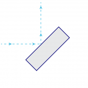
Coating Optimisation for Oblique Incidence
Dielectric multilayer coatings for 45° beam steering are engineered specifically for oblique operation rather than adapted from normal-incidence designs. This allows:
- High reflectivity at the specified wavelength.
- Stable behaviour in random polarisation.
- Controlled mechanical stress within the coating stack.
- Reliable operation in demanding laser environments.
The coating architecture is therefore optimised for consistent reflectance and system efficiency at 45°.
Optical and Mechanical Specification
- Substrate: UV Fused Silica
- Diameter tolerance: +0 / −0.25 mm
- Thickness tolerance: ±0.25 mm
- Front surface flatness: λ/10
- Surface roughness: <0.8 nm RMS
- Front surface quality: 10-5 scratch dig
- Rear surface: Inspection polish
- Reflectivity: Greater than 99.3% at the specified wavelength in random polarisation.
To provide additional rigidity for oblique beam steering, these mirrors are manufactured approximately 10% thicker than equivalent 0° cavity mirrors.
Surface flatness is verified after coating using interferometric measurement to confirm that coating stress has not degraded optical figure.
Laser Induced Damage Threshold (LIDT)
Laser induced damage threshold performance is characterised according to wavelength and pulse regime.
- Test wavelength: 1064nm
- Pulse duration: 10ns
- Test protocol: ISO 21254, S-on-1
- Measured LIDT: 35 J/cm² at 10Hz
Full test methodology and supporting data are available during technical evaluation.
Standard Wavelengths
High reflectivity dielectric coatings are available at:
- 248nm
- 266nm
- 355nm
- 532nm
- 1030nm
- 1064nm
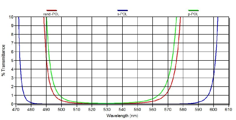
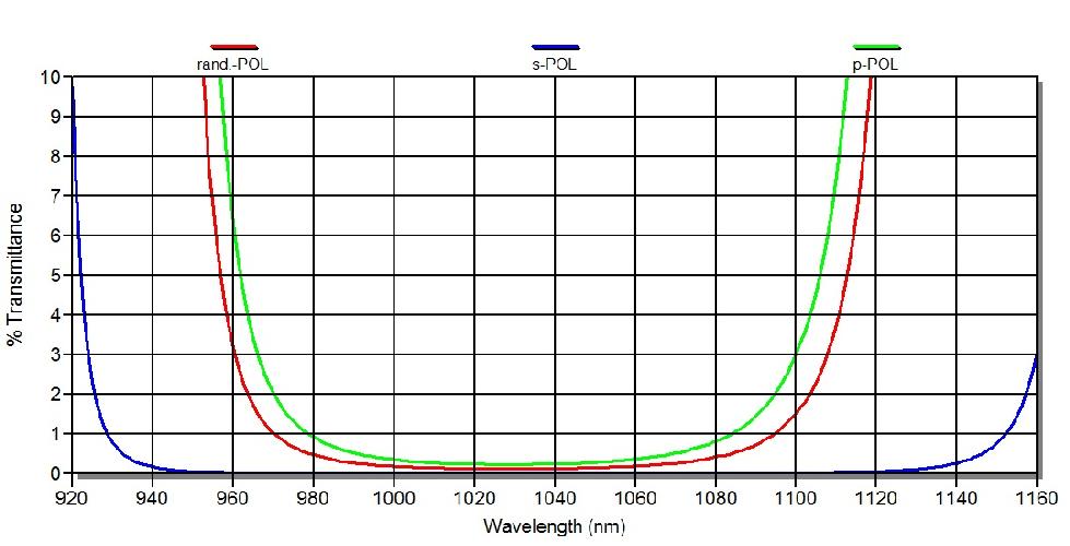
Reflectance curves are available for each wavelength.
Other wavelengths are available on request.
Standard Dimensions and Part Numbers
Retain full part number table exactly as currently structured on the live 45° page.
Other sizes and specifications are available on request.
Coating Architecture and Process Control
These mirrors utilise dielectric multilayer high-reflectivity coatings engineered for oblique-angle performance.
Coating deposition processes include:
- Electron beam evaporation.
- Ion Assisted Deposition (IAD).
Process monitoring ensures accurate layer thickness control and repeatable spectral performance across production batches.
Metrology and Inspection
Each component is verified through structured inspection procedures including:
- Interferometric surface figure measurement (6” and 18” interferometers).
- Surface quality inspection to 10-5 scratch dig.
- Reflectivity measurement at the specified wavelength.
- Witness samples and spectral curve documentation for each coating run.
Inspection reports can be supplied to support qualification and procurement review.
Manufacturing Control and Repeatability
All optics are manufactured within a controlled production environment with documented procedures covering:
- Substrate preparation
- Precision polishing
- Cleaning and contamination control
- Coating deposition
- Post-coating inspection
- Batch identification and traceability
These procedures support consistent, repeatable supply for OEM and research programmes.
Typical production lead times range from one week for standard off-the-shelf products to approximately eight weeks for custom specifications, depending on quantity and requirement.
Custom Solutions
Custom configurations are available, including:
- Alternative diameters and thicknesses
- Custom wavelengths
- Application-specific reflectivity targets
- Enhanced flatness tolerances up to λ/20
- Integration into larger optical assemblies
For cavity mirrors engineered for normal-incidence laser systems, see MPO’s 0° incidence laser line mirrors.
Whether you know exactly what you require or wish to discuss your application with the MPO technical team, please get in touch.
HR @ 248nm /45º
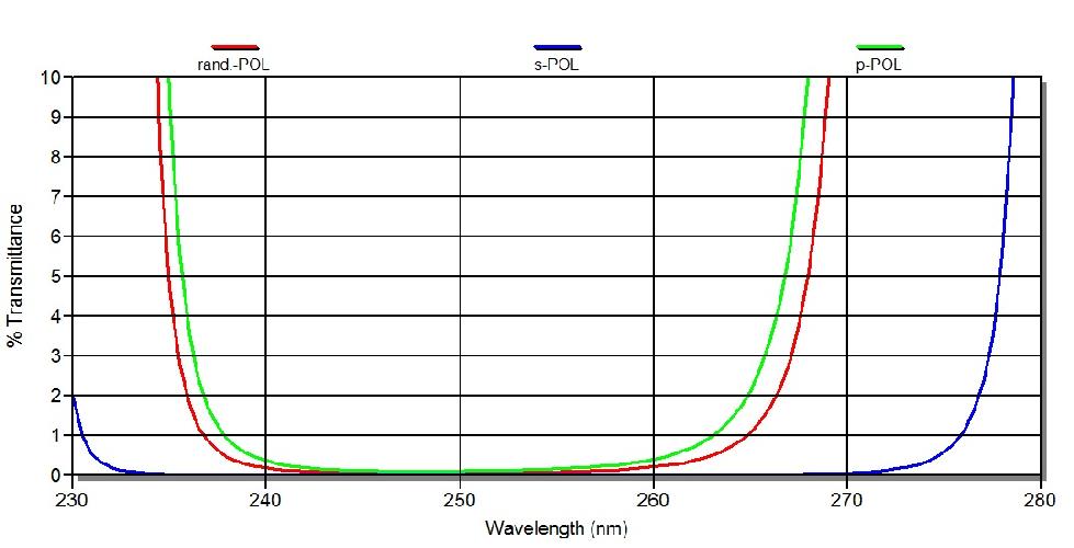
HR @ 266nm /45º
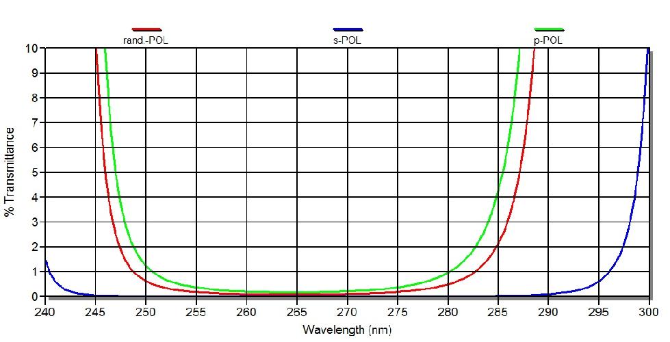
HR @ 355nm /45º
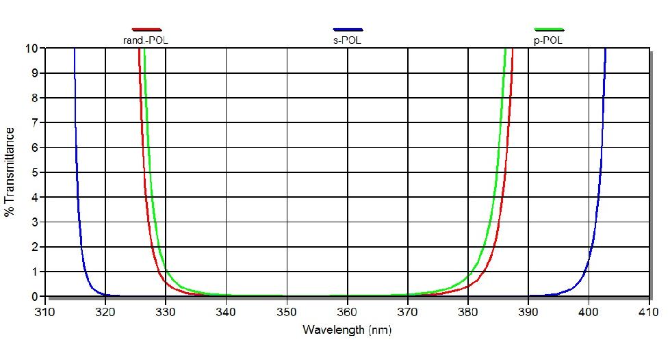
HR @ 532nm /45º
HR @ 1030nm /45º
HR @ 1064nm /45º

PART NUMBER |
DIAMETER (D) |
THICKNESS (T) |
COATING WAVELENGTH |
FS-FMR-25.4-6.35-HR-248-45 |
25.4mm |
6.35mm |
248nm |
FS-FMR-50.8-9.52-HR-248-45 |
50.8mm |
9.52mm |
248nm |
FS-FMR-101.6-12.7-HR-248-45 |
101.6mm |
12.7mm |
248nm |
FS-FMR-25.4-6.35-HR-266-45 |
25.4mm |
6.35mm |
266nm |
FS-FMR-50.8-9.52-HR-266-45 |
50.8mm |
9.52mm |
266nm |
FS-FMR-101.6-12.7-HR-266-45 |
101.6mm |
12.7mm |
266nm |
FS-FMR-25.4-6.35-HR-355-45 |
25.4mm |
6.35mm |
355nm |
FS-FMR-50.8-9.52-HR-355-45 |
50.8mm |
9.52mm |
355nm |
FS-FMR-101.6-12.7-HR-355-45 |
101.6mm |
12.7mm |
355nm |
FS-FMR-25.4-6.35-HR-532-45 |
25.4mm |
6.35mm |
532nm |
FS-FMR-50.8-9.52-HR-532-45 |
50.8mm |
9.52mm |
532nm |
FS-FMR-101.6-12.7-HR-532-45 |
101.6mm |
12.7mm |
532nm |
FS-FMR-25.4-6.35-HR-1030-45 |
25.4mm |
6.35mm |
1030nm |
FS-FMR-50.8-9.52-HR-1030-45 |
50.8mm |
9.52mm |
1030nm |
FS-FMR-101.6-12.7-HR-1030-45 |
101.6mm |
12.7mm |
1030nm |
FS-FMR-25.4-6.35-HR-1064-45 |
25.4mm |
6.35mm |
1064nm |
FS-FMR-50.8-9.52-HR-1064-45 |
50.8mm |
9.52mm |
1064nm |
FS-FMR-101.6-12.7-HR-1064-45 |
101.6mm |
12.7mm |
1064nm |