This technical note provides readers with an overview of the physics of optical polarisation followed by a brief description of the different components which can be used to achieve polarisation and control polarised light.
Polarisation, the main subject of this technical note, is a fundamental property of waves. Transverse waves can have many polarisation orientations whereas longitudinal waves like sound waves only have one. Optics generally deals with transverse electromagnetic waves so these will be examined in more detail. Polarisers are the other subject of this note. These are optical instruments that are used to polarise light and are utilised in a variety of ways such as in photography to reduce reflection from reflective surfaces.
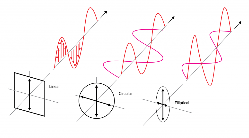
A transverse electromagnetic wave consists of electric and magnetic fields which oscillate perpendicular to each other and the direction in which the wave is travelling. These transverse waves can be described by a sinusoidal function. One can think of light as a sine wave oscillating about a line pointing in the direction the light is travelling. The simplest case is when the electric field oscillates back and forth in a fixed direction as depicted on figure (1).
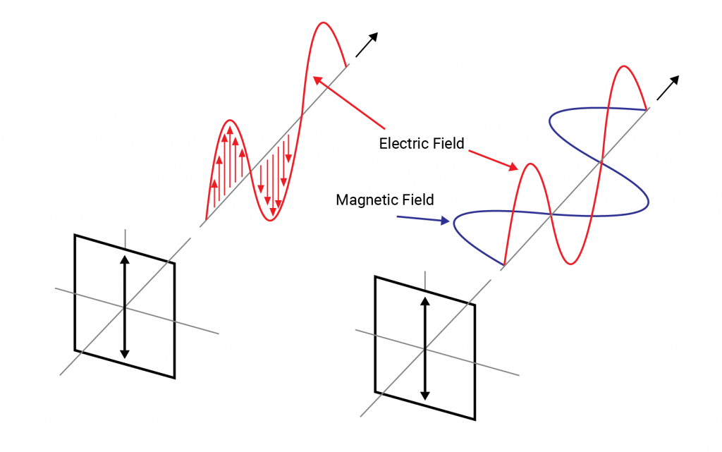
This is known as “linear polarisation”. The most general state of polarisation consists of two such linearly polarised waves travelling out of phase with each other and with different amplitudes. Such light is known as “elliptically polarised” referring to the elliptical shape traced out by the electric field as it travels. There is a third polarisation state known as “circularly polarised light” which is the particular case where the waves are 90 degrees out of phase and possess identical amplitudes such that they produce a circular or cylindrical shape through space as they propagate. Circularly polarised light can be “left or right handed” depending on the direction the field rotates about the axis of propagation.
S and P polarised light
Light incident upon a surface can be decomposed into two linear polarisation states with electric fields oscillating parallel and perpendicular to the plane of incidence. These components are known as P (for parallel) and S (from the German word for perpendicular, senkrecht) polarised light. To avoid confusion with the discussion on polarisation above it should be made clear that S and P polarisation refers to the orientation of a wave with respect to a particular surface, whereas linear, circular and elliptical polarisation refers to the phase difference between the orthogonal electric field components of the wave.
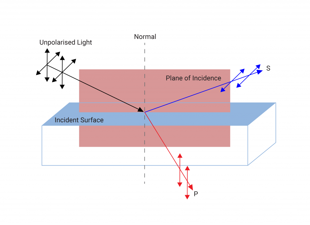
In the case of normal incidence this distinction is unimportant however at oblique incidence the S and P polarised components may behave differently. For example, Brewster’s angle is the angle at which p-polarised light is perfectly transmitted through the surface in question and is given by θB = tan-1 (n1⁄n0) (where n0 is the refractive index of the surrounding medium and n1 is the refractive index of the incident medium). The result of this is that when randomly polarised light is incident at Brewster’s angle, the partially transmitted reflected light will be s-polarised and the transmitted light will remain both s and p polarised, with a smaller fraction transmitted as s pol. This means that by placing multiple plates at Brewster’s angle in a line will eventually result in a fully s-polarised beam of reflected light and a p-polarised beam of transmitted light. Practically one would have to put a large number of plates in a line to achieve this, so it is rarely used nowadays for polarisation.
In the MPO catalogue, one will find the polarisation of a ray described in 3 ways; s-POL, p-POL, and Rand-POL. The first two refer to the s or p polarisation states of the ray discussed above, and the third references unpolarised light (a mix of s and p polarised light).
Polarisers
There are numerous methods for achieving polarisation, though the function of all polarisers is the same; to let through only light of a certain polarisation whilst the rest is either reflected or absorbed. In this section we refer to cube and plate polarisers, beamsplitters retarders and waveplates.
In an ideal case, given an incident, randomly polarised beam the polariser lets the component of the light oriented with the polariser through, though realistically some light may be absorbed or a small amount of unwanted polarisation let through. Given an incident polarised beam (achievable with an additional polariser like in figure 4) the polariser performance is then prescribed by (1) and (2)
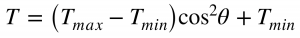
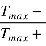
Where TMax and TMin are the maximum and minimum transmittances and θ is the angle between the polarisation of the incident beam and that of the polariser. We see that at 90° this intensity is reduced to TMin as most of the light is absorbed or reflected at this orientation. Conversely at 0° the polariser is oriented completely with the incident polarisation and the maximum amount of light is let through.
The value P is known as the polarisation efficiency, for an ideal polariser P=1. Another value commonly used to describe polariser performance is the extinction ratio TMax⁄TMin or sometimes TP⁄TS for s and p polarisers.
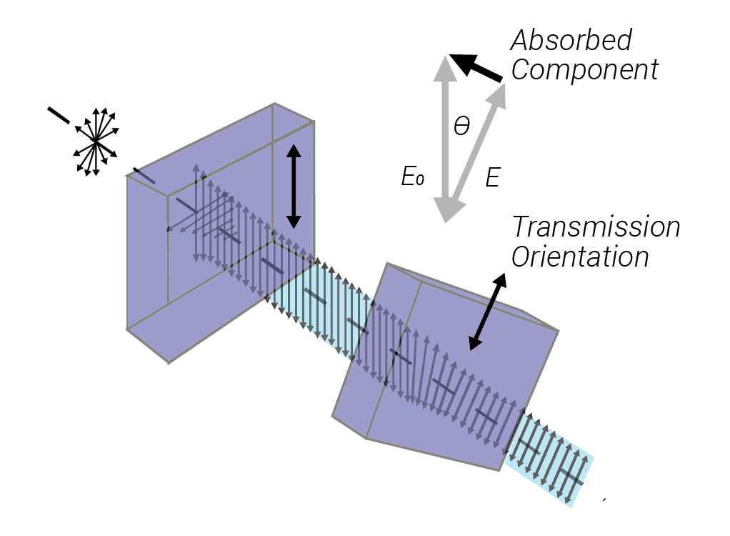
A polariser that absorbs unwanted polarisation states is known as a dichroic polariser. Perhaps the best-known example of such a polariser is the polaroid filter which is commonly used in LCD displays and sunglasses. Such a polariser is unsuitable for use in the presence of highly intense lasers due to their absorptance. It is however possible to construct dielectric polarisers with high LIDT based on Fresnel reflectivity.
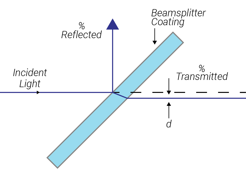
A dielectric polariser such as a plate polariser or beam splitter film relies on thin film interference to achieve polarisation. The width of the reflectance zone of a HR coating depends on the ratio of the indices of refraction/optical admittances which are different for s and p polarised light at non normal incidence. It can be shown that for such a coating the width of the high reflectance zone for p-polarised light is then always less than for s-polarised light. The wavelength region where the reflectance drops for p-polarisation may therefore lie inside the region where s-polarised light is still reflected leaving a small region where the p-polarised light is fully transmitted and s-polarised light is fully reflected. This makes such a filter ideal for single wavelength operations such as a laser line.
Plate polarisers consist of a substrate coated with a high reflectance coating (or any coating with a sharp edge between high transmission and high reflectance) and function as depicted in figure 2. A typical extinction ratio for such a polariser is 10-2
.
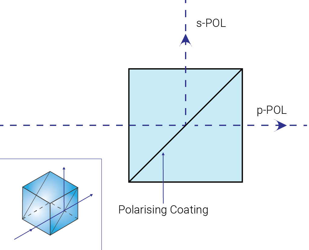
Another widespread and common dielectric polariser is the beam-splitter cube. The beam splitter cube consists of a pair of optically contacted or cemented prisms with a dielectric multilayer stuck between them and the outside coated with an AR coating. A coating immersed in prism material has a reduced Brewster’s angle, enhanced polarisation splitting and a broader polarising region than with air as the incident medium, and is capable of separating unpolarised light into very highly polarised out-put beams at an almost 90° angle. The extinction ratio of a typical beam splitter cube is around 10-2 – 10-3 .
.
The polarisation and orientation of a wave can be manipulated via “retarders”. These are optical devices that introduce an optical path difference (OPD) between the orthogonal components of a wave, and are therefore capable of transforming anyone polarisation type into another. A common example is the waveplate, which often comes in the form of a slab of (ideally uniaxial) birefringent material such as quartz or mica. In birefringent materials, incident light is split into two beams of orthogonal polarisation which experience different refractive indices and therefore, depending on the plate thickness induces a phase shift between the two orthogonal components. In a waveplate, the crystal is cut so that the optical axis is perpendicular to the optical axis of incident light and parallel to the incident surfaces, meaning that the light is not split into beams heading off into different directions but merely picks up a phase shift, changing the polarisation state.
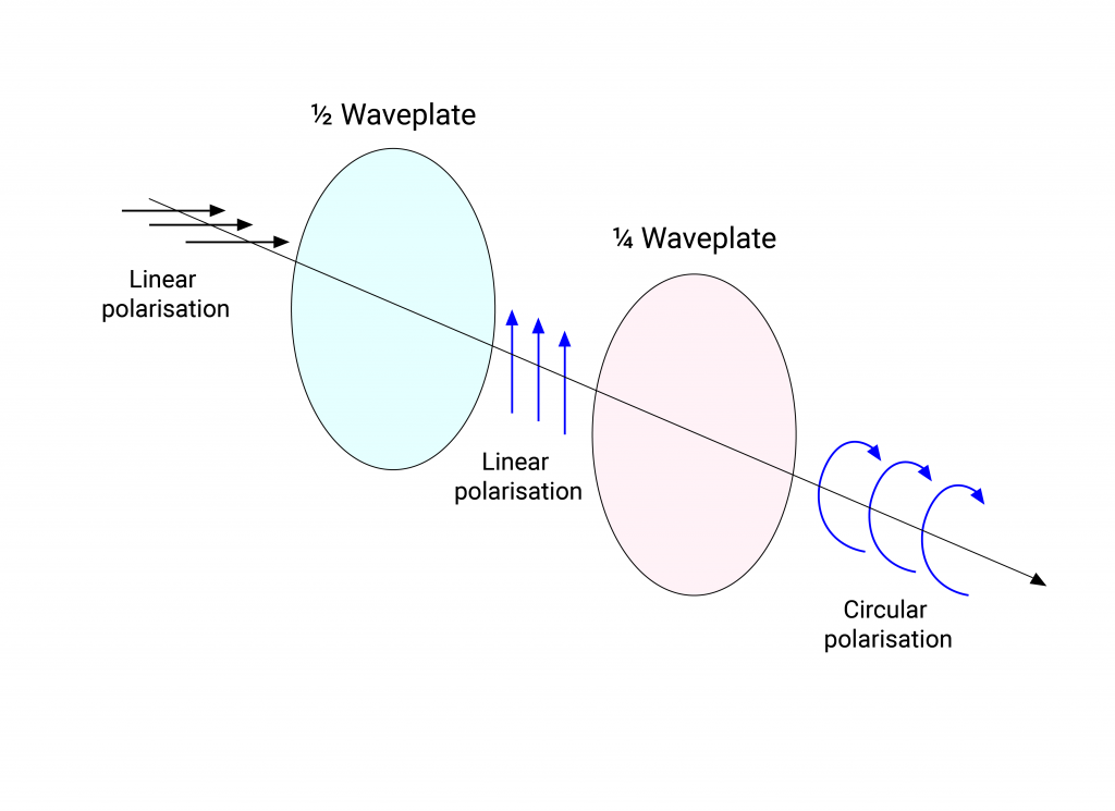
Figure 7 depicts two standard waveplates, the quarter-wave and half-wave plates. A half-wave plate introduces a phase shift/retardation π which simply rotates linearly polarised light about the axis of propagation by twice the angle between the direction of oscillation and the optical axis of the crystal. A half-wave plate can therefore be rotated to transform linearly polarised light into linearly polarised light of any orientation. A quarter-wave plate likewise introduces a retardation π⁄2 meaning that incident linearly polarised light is transformed into a circular polarisation state. Waveplates are referred to as “multi-order” or higher-order when the phase difference is some integer multiple of π or π⁄2.
MPO manufactures and produces optical prisms, beam-splitter plates and optical coatings for polarisers. Our polarisers come in a variety of different dimensions and we have a range of polarising and anti-reflection coatings with operational wavelengths across the UV, visible and infrared bandwidths, as well as ultrafast variants with extremely low GDD. We also manufacture high precision waveplates. If you have any inquiries concerning polarisers or waveplates then do not hesitate to contact us.
References and Further Reading
Handbook of Optical Systems Volume 5, H. Gross (ed.), Wiley-VCH Verlag GmbH & Co KG, 2012, ISBN 978-3-527-40381-3
Thin-Film Optical Filters Third Edition, H. A. Macleod, Institute of Physics publishing, J W Arrowsmith LtD. Bristol, 2001, ISBN 0 7503 06887 2
Hyperphysics, R. Nave, http://hyperphysics.phy-astr.gsu.edu/hbase/phyopt/polclas.html