This white paper provides a detailed look at the intricate process of transforming raw glass into high-quality optical components. We discuss the five steps involved, from shaping the initial glass piece to achieving a near-perfect finish.
The fabrication of precision optics is an involved process requiring extensive shaping, grinding and polishing. If required, finishes with Angstrom scale (〖~10〗^(-10)m) surface roughness (RMS) are achievable. The techniques, science and machinery of glass fabrication is a complex subject and so the purpose of this technical note is to provide a general overview of the process. The specifics and subtleties of optical glass fabrication are covered in additional technical notes.
Chapter 40 of the Handbook of Optics Vol. 1 (1995), Optical Society of America (now Optica), lays out the five steps of optical fabrication as:
- Rough shaping – shaping of raw glass into a blank approximately 1mm larger than the finished part
- Milling – further shaping of optical surfaces to better than 0.1mm and preparation for polishing
- Loose abrasive lapping, grinding – grinding or “lapping” of the optic to remove damage from the previous step and shape the optic to within a few micrometres of desired curvature
- Polishing – polishing of the ground surface to the desired finish quality
- Edging – realignment of the optical axis joining the two optical surfaces and the mechanical axis of the optic.
These steps mainly apply to the fabrication of curved components however many are also applicable to plano-optical surfaces.
Rough Shaping
An optical component will generally begin life as a slab of glass produced by a manufacturer and first sawn, and then ground. At this stage the optical blank is very roughly the shape of the finished component but generally larger than the final piece. Optics can be rounded either manually or via machine rounding, the latter being more economical in most cases. Rounding accuracies of ±0.050mm are common in the industry. These roughly shaped pieces come in a variety of shapes, sizes and compositions, with properties such as refractive index, Abbe number (dispersion) and dimensions specified by the component manufacturer.
Grinding
Blanks straight from a materials manufacturer are very rough and as stated above, should be larger than the design of the final optical component. To prepare them for grinding and polishing they must undergo a grinding process where they are ground down and shaped to bring them close to the dimensions and curvature of the final optic. Grinding is a collective term for “curve generating” and “plano milling” (grinding on a surface grinder) also called “fine grinding”. If the final piece is a lens or other curved optic then curve generators are required. These devices consist of two spindles, one to hold the workpiece and the other to hold the diamond cup-shaped grinding wheel which generates the curve. Generation proceeds by either rotating the workpiece at a high rate and allowing the cup-wheel to grind against it at a lower rate or by allowing the diamond tool to cut into the glass and generate a curve at the depth of the cut. In both methods the radius of curvature is determined by the angle at which the wheel is positioned relative to the mechanical axis of the blank.
Plane surfaces are ground according to a method based on surface grinder in machining. The setup consists of a rotating workpiece table and a diamond face wheel. Once loaded, the workpiece table is adjusted and moved underneath the diamond wheel. The wheel is then adjusted and lowered until it contacts the rotating table at which point it rotates and the grinding proceeds until the desired amount of material is removed. A typical surface grinder consists of an 11in./27.04cm diameter diamond wheel which rotates at 1200rpm and a 20in./50.8cm diameter workpiece table which rotates at adjustable speeds such as 15, 24, 41 or 64rpm. Grinding machines tend to be very large and rigid hence they are capable of grinding many workpieces simultaneously to a high and repeatable standard of accuracy. Prism grinding requires diamond tools mounted on machines with adjustable spindle angle and height due to the specific angles involved in the design of a prism.
The methods outlined above can be described as ‘coarse grinding’ operations contrasted with so-called “fine grinding”. Fine grinding involves spherical laps that are studded with diamond pellets and comes after the initial shaping via coarse grinding. Workpieces are mounted onto a convex or concave arm which grinds against the diamond riddled surface. Finely ground surfaces tend to have pores only 2-3μm deep and polish out faster than surfaces ground with loose abrasives, however it is a much more expensive process.
All grinding processes require a liberal supply of liquid coolant to be applied to the workpiece and diamond tool otherwise they will heat due to friction, causing potential damage to both the machine and the workpiece. Coolants should possess highly lubricating properties to reduce wear on the diamond tool and should have a low viscosity, enabling it to carry away eroded material.
Being simply a piece of glass fresh from a factory, a blank is understandably very rough and will not be in the desired shape of the final optic, so shaping the blank is traditionally achieved via “generating” where cup-shaped grinding wheels generate the concave or convex shape of a lens, the radius of curvature being determined by the angle at which the wheel is positioned relative to the mechanical axis of the blank. A surface mill often consisting of a diamond or abrasive face wheel is a staple of optical workshops as it is generally used to prepare plano-surfaces. The work piece can be either a single part or a (large) number of small parts fixed to a rotating table beneath the wheel. With the table spinning, the wheel is lowered until it touches the optics and the milling process begins. Numerous machines with adjustable angles exist for the shaping of plano-prism surfaces.
Loose Abrasive Lapping
With the glass now in roughly the right shape it undergoes loose abrasive lapping (sometimes known as loose abrasive grinding) to remove fractures caused by shaping and to improve the overall sphericity. Before this is done, the edges of the optic are bevelled to avoid small pieces of material chipping off and scratching the surface. The lapping process removes stock via the friction between the glass and the lapping plate in conjunction with a combination of water and grit. The grains in the resultant slurry move back and forth, the sharp edges penetrating the surface of the workpiece. This introduces tiny, local fractures into the surface of the glass, leading to splintering and the removal of material as well as introducing pits into the surface. The size of the individual grains in the slurry can vary from around 3μm up to around 300μm, with a larger grit size leading to a faster removal rate at the cost of a rougher finish. As a result, lapping often begins with rougher solutions in a process known as roughing with grain sizes of at least 120μm followed by a pre-grind (45-80μm) where surface roughness and shape are improved, and centre thicknesses brought to exact dimensions. The workpiece then proceeds to the pre-fine (15-35μm) stage followed by fine grinding with grit size 3-12μm. As small grains produce pits that are about half their diameter the surface is refined to a micrometre scale surface roughness by the end of the process.

Grinding tools can be either spherical or plano and are generally made of cast iron. They are designed for use with specific grain sizes, for example a typical set of grinding tools for use with specific grain size is given by table 1.
Tool Type |
Abrasive grain size μm |
Roughing |
115-230 |
Pre-grinding |
45-75 |
Pre-fine |
17-29 |
Fine-grinding |
3-13 |
Table 1: A typical set of grinding tools
Polishing
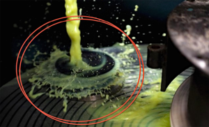
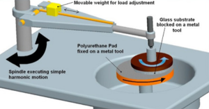
The next stage of the optical fabrication process is known as ’polishing‘. It is at this stage that optical components will reach their final shape and acquire a transparent, optical quality finish. The best possible surface finishes are possible through a polishing process referred to as ’pitch polishing’. Pitch polishing achieves a high-quality polish on glass, like lapping, but uses a a lap composed of pitch and a watery slurry containing oxide-based polishing compounds. The pitch covers a circular ring or platform and rotates around with the workpieces affixed to a moving overarm or resting in a jig held by the overarm. Grooves are cut into the pitch to encourage a steady flow of slurry between the lap and the optic. These grooves should be inspected and re-cut frequently as the pitch is worn and down and warps over time. Weight has a significant influence on the rate and quality of the polishing process and so optics should be catered to depending on weight by, for example, placing weights atop a workpiece or overarm.
Pitch is a unique, viscoelastic compound which occurs naturally but can also be produced synthetically, the basic types being wood pitch (deciduous and coniferous), rosin-based (green and yellow), petroleum-based, and asphalt tar pitch (coal-based). Over time the pitch will conform to the shape of the optic, smoothing it without causing deviation in the radius of curvature/sagitta. Pitch can have a variety of hardness’, where hard pitch is more effective for high speed polishing, smaller workpieces, convex surfaces and standard quality optics whereas soft pitch is more effective for the low speed polishing of large workpieces, high precision optics and concave surfaces. The microscopic mechanism behind polishing is thought to be down to the chemical and mechanical reactions between the slurry and glass. Through the energy provided by friction the oxide slurry is thought to chemically soften the surface of the optic down to a depth of a few nanometres such that it is dissolved into the water or worn away mechanically by the action of the slurry on the glass. It is through these mechanisms that surface roughness is improved, decreasing it from the micrometre scale down to 1nm rms or even less.
Centring
The last step in the fabrication of precision optics is lens centring and edging. Even though by this point the surface finish and curvature of the optic are extremely high quality the process outlined above may introduce a slight wedge of a few minutes of an arc. This means that the optical axis between the centres of curvature of a lens does not coincide with the actual mechanical axis and must be corrected.
One method for re-aligning the axes is the ‘transfer spindle’ method where a lens is mounted on a mandrel fastened to a spindle such that either the mechanical or optical axis is aligned with the axis of the mandrel. The spindle, mandrel and lens are then mounted to a centring machine which grinds the diameter of the lens concentric to the axis of rotation. This method can be carried out either optically or mechanically. Another method, known as ‘bell chucking’ consists of clamping a lens between two precision aligned brass mandrels or bell chucks. As the chucks rotate and grind the edge of the lens it will naturally position itself such that the edges are ground to a point of equal thickness, thus making the optical and mechanical axes co-linear. Bell chucking is depicted in figure 4 below.

MPO is equipped with facilities for the shaping, grinding, polishing and edging/bevelling of optical glass. Colleagues working in our glass fabrication department have decades of experience and are capable of achieving surface finishes with RMS roughness’s as low as ±0.2nm (2Å). If you would like to inquire about the grinding and polishing of your optic and the associated labour, machining and material costs then please do not hesitate to contact us on sales@mpo.im or via mpo.im.
References and Further Reading
Neauport, J Destribats, et al. Loose Abrasive Slurries for Optical Glass Lapping, Journal of Optics A: Pure and Applied Optics, IOP Publishing, 2010, 49, pp.5736-5745. ff10.1364/AO.49.005736ff. ffcea01217069f.
The Handbook of Optics Vol. I, M. Bass, R. E. Parks et. al., Optical Society of America (now Optica), McGraw Hill Inc. (1995) ISBN 0-07-047740-X.
Fun Facts about Pitch and the Pitfalls of Ignorance, B. E. Gillman F. Tinker, Zygo Corporation Proceedings Volume 3782, Optical Manufacturing and Testing III; (1999) Event: SPIE’s International Symposium on Optical Science, Engineering, and Instrumentation, 1999, Denver, CO, United States Fabrication Methods for Precision Optics, H. H. Karow, Wiley Series in Pure and Applied Optics, John Wiley & Sons, Inc (1993).